My Machine Shop
My shop’s lathe is a 7 x 12 Chinese lathe imported by Micro-Mark. This company has a great selection of precision quality tools especially considering their smallish size, which generally infers either poor quality or toy status – definitely not the case with these tools. Sadly the Chinese lathe could be better quality, but in this size range, there is little else except the English Myford, which is almost unobtainable due to high cost. Prior to the Chinese (Sieg) lathe I had a Sakai lathe. Sadly Sakai abruptly existed the market orphaning their product. For those orphan owners in need, here is a PDF of the Sakai manual.
In addition there is a Sherline vertical milling machine and other small power tools.

Model engines

Sherline Mill on homemade lazy susan. The lazy susan helps me access the machine for setup.

Chinesse lathe. Note access for wheelchair under bench.

Another work area with wheelcahir access.

Models I have made from casting.

PM Research dynmo from casting.

Stuart Turner steam engine made from castings.

Hit or miss engine based on Sears economy.

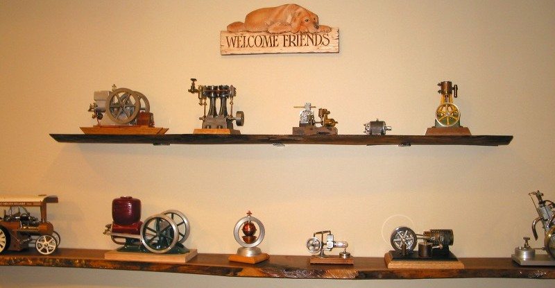
More displays and misc junk

DRO modification on Sakai lathe

Modifyed handwheels for DRO

Sakai lathe now replaced with Chinese lathe

Completed DRO retrofit

Small hand tools

Staurt Turner engine I machined/built form casting.

Tach for DRO

The manual for Old Model Company OMC-5 motor.

The little bits – neatly packed in numbered bags by build step.

The walnut base overlayed with a copy of the hole template spray adhesived to the base. The red X just kept me from re-drilling the smaller holes.

The base with mounting holes drilled ready for test fitting.

The base with the coil mounts installed. The instructions suggest mounting the coils after the base but I will reverse that sequence.

The base with mounts and coils.

Flywheels with the 4 ferris bits that form the armature. These are the bits that the magnets attract.

Another view of the flywheel.

More bits installed.

The contactor points – assembled (more photos later) they switch power to the coils which attract the ferris bits. Operated by a 4-sided cam.

The main power switch – the little little tiny bits for my fat fingers to assemble.

The motor mocked up – a few parts need to be test fitted – then disassemble for paint and final finishing, though many of the bits are well finished.

Placing the contactor bracket onto the base. Precision drilling the holes is made very clear at this step.

Contact assembly installed onto bracket with slotted machine screws. Insulator not placed at this mock-up stage, is needed for final assembly.

Prototype assembly completed – about 2 hours or so, now will reflect on color of paint and breakdown for final finishing steps. Don’t know when…

Now will reflect on choice of color for paint and breakdown for final finishing steps.

Side view of mocked up assembly. Somthing less than 2 hours time at this point. As a guess a good father (or mom) son project age 11-12 or so.

The remaining little bits.

By the mid 1800’s several versions of this arrangement had been tried and the OMC-5 Revolving Armature Engine is an such an example.

The completed flywheel.

The bits that comprise the contactor assembly.

Placed into the plastic shell.

The contactor with the rubber pad insulator.

Contactor assembly placed onto the contactor base.

Both contactors now positioned.

A-frame, contactoers and the name plate.

Side view of the contactor assembly

The completed on/off switch.

The model assemble is done and now ready for wiring.

The base with DIN style terminal strips. If I was to do this over, First I would attach the magnet wires, then position the strip to the base.

The aftermath of a narrow brush with “death” – dumb me. Moral – don’t ‘open all (ok most of them) of the drawers at once!

The completed wiring, messed up a couple of colors runs – doesn’t affect operation – just affirms the fact I can’t follow instructions.

Nestled amongst the other time-wasters constructed over the years.
Watch the video of the completed project!